This guide is for the standard Orion BMS (metal unit with heatsink), pictured below. If you have a plastic Orion Jr. BMS unit, please click here for troubleshooting steps.
Diagnosing communication problems can be frustrating since there are many possible causes, and communication either works or doesn’t work. The following steps resolve most communications problems. Please attempt the following steps before contacting Ewert Energy for support.
Resolving the issue:
Step 1. Ensure the BMS is connected using the CANdapter by Ewert Energy Systems.
The BMS can only be connected to the computer using the Ewert Energy Systems CANdapter. Other CAN to USB adapters are not compatible. The CANdapter can be purchased here.
Step 2. Ensure that you are using the correct BMS utility. The Orion BMS utility must be used to connect to a standard Orion BMS unit. Please ensure that you are not inadvertently using the Orion Jr BMS utility. The correct utilities can be downloaded from the “Downloads” section of the Orion BMS website.
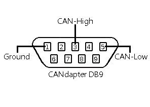
Step 3. Ensure that you are connecting the correct pins to the CANdapter. The CANdapter uses pins 3 and 5, which differs from some other CAN to USB adapters. Pin 3 is CAN-High, pin 5 is CAN-Low, as shown below. It is very easy to get these backwards by mistake so please examine this carefully. The diagram below is taken from the perspective of the wires coming out towards the viewer from the female end of the DB9 connector.

If the “Connect to BMS” dialog says “None Found,” the problem is between the computer and the CANdapter (otherwise skip to step 5.)
1) The CANdapter driver may not be installed or may not be working correctly. Most computers will come with the driver pre-loaded, but some need the driver manually installed. The driver can be downloaded from here:
https://www.ewertenergy.com/products.php?item=candapter&page=drivers
2) The CANdapter may not be connected to the computer via USB. To make sure that the CANdapter is connected, disconnect it and then plug it back in. While re-connecting it, look for three rapid flashes of both the red and green CANdapter lights. If the lights do not flash, try using a different USB port or cable. If the problem cannot be resolved, try using a different computer. If the LEDs still do not flash when the CANdapter USB port is connected even after using a different cable and computer, there may be a problem with the CANdapter.
Step 5. Verify the correct baud rates.
The Orion BMS and CANdapter can operate at various baud rates including 125kBps, 250kBps, 500kBps, and 1000kBps. The BMS units are shipped operating at 500Kbps by default. However, the baud rate setting on the BMS can be changed in the settings profile. The baud rate of the CANdapter and the BMS must match for successful communication.
Important: All devices on a CANBUS MUST communicate at the same baud rate. If any device(s) on the CANBUS communicate at different speeds, the bus will become garbled and completely unusable for all devices on the bus. If there are devices on the network operating at different frequencies, it will be necessary to remove those devices from the bus network until they are all set for the same frequency.
If it is necessary to change the baud rate of the Orion BMS unit, it will need to be disconnected from other CANBUS nodes and programmed directly (or other nodes on the network powered down first). Alternatively, it may be possible to use the other CANBUS interface on the BMS to update the baud rate. Note: After baud rates are changed in the settings, the Orion BMS must be power cycled for the new baud rate to take effect. The same can be accomplished by connecting to the BMS and selecting File → Restart BMS in the Orion BMS utility)
It may be useful to attempt to connect to the Orion BMS unit directly (with no other CANBUS nodes) at all the different baud rate settings in the event that the baud rate is set differently than expected.
Step 6. Ensure the BMS is powered when connecting to the BMS.
The BMS requires power in order to respond to the communication. At a minimum, +12V (actual voltage of 9 – 16V on the original Orion BMS or 9 – 30V on the Orion BMS 2) must be applied to either the READY power source (Main I/O connector pin 2 – solid blue wire) or CHARGE power (Main I/O pin 3 – solid red wire). The Ground pin (Main I/O connector pin 12) must be connected to the power supply’s negative.

Orion BMS 2 units have an LED mounted next to the Main IO connector that is useful for determining if the unit is powered. If the LED is off (not red or green) then this indicates that either the unit is not powered or that it is in deep sleep (either Charge Power or Ready Power must be energized for the BMS to be awake and operational). The color of the LED indicates whether any faults are present (green = no faults, red = 1 or more fault present).
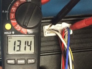
Additionally, the power consumption of the unit can be checked to verify that the BMS is operating. This can be done by measuring the DC current used by the BMS with an ammeter or multi-meter with a DC current measurement feature. The current going into the power supply pin should be over 100mA and below 300mA. If power consumption is 0mA, the unit may not be receiving power or may have an internal problem. If the unit does not power up, contact Ewert Energy for evaluation / repair options.
Step 7. When trying to connect to the Orion BMS, check the status of the LEDs on the CANdapter.
If the red LED on the CANdapter comes on and stays on when trying to connect there are errors present on the CAN bus. This can indicate CAN high and CAN low are backwards, the bus is shorted, there are devices operating at different CAN frequencies, that there is improper termination, that the wrong type of cable is used or that there are other wiring problems. If the CANdapter LEDs don’t come on, verify that the CANdapter is properly connected. The green and red LEDs should flash a few times when the CANdapter is first connected. Proceed to step 8 to diagnose CANBUS wiring errors.
Step 8. Ensure proper wiring of the CAN bus, including proper termination of the bus.
Many problems with CAN communication turn out to be wiring issues on the CANBUS, many of which visually appear to be correct. Since CANBUS is a high speed communication network, it is sensitive to proper wiring. First, verify CAN_H and CAN_L are not backwards. To verify the correct connection, with both connectors disconnected, use a continuity tester to ensure that pin 3 on the DB9 connects to pin 18 on the BMS connector and pin 5 on the DB9 connects to 19 on the BMS connector (assuming the CAN1 interface is being used.) If CAN2 is being used pin 3 on the DB9 should connect to pin 21 on the Main I/O and pin 5 on the DB9 should connect to pin 21 on the Main I/O connector.)
If continuity is good, verify proper CANBUS termination. The CANBUS will not operate correctly unless exactly two (2) 120 ohm resistors are the the 2 physical ends of the CANBUS. To test for proper termination, completely remove all power from all devices on the CANBUS and measure the resistance between CAN High and CAN Low. It should read 60 ohms (Qty 2 120 ohm resistors in parallel will result in 60 ohms of total resistance.) If the resistance readings are not 60 ohms, something is wrong with the termination. A value lower than 60 may indicate that there are too many termination resistors. A value of 120 ohms indicates only one termination resistor is present.
Note: The Orion BMS ships standard with a termination resistor on the CAN1 interface and without a termination resistor on the CAN 2 interface. Special order units may be configured differently.
Important: Exactly one CAN 120 ohm termination resistor MUST be at each physical end of the bus to work properly (total of two resistors)! We receive many inquiries from customers who assume it will work properly without resistors or work with only one and find that they are unable to communicate with the BMS or find that it only works intermittently. If you only have one termination resistor, please add proper termination before inquiring for help as this solves the majority of communication issues.
The physical layout of a CAN bus matters significantly as this is a high speed communication bus. Wire *must* be twisted pair cable with no sections larger than about 1 inch (2cm) of untwisted cable (shielded twisted pair is preferred). Wires must be firmly connected (do not press wires together or use breadboards or phone blocks). Ensure that taps off the main trunk of the bus are kept to 2ft or less (see the wiring manual for more information about CAN bus wiring). Do not connect CANBUS nodes in a star configuration. Note that simply because there is continuity between the pins does not gaurentee that the cable is of sufficient quality for high speed communication.
More tips for locating and resolving CANBUS wiring problems please see the below document:
https://www.orionbms.com/general/diagnosing-canbus-communication-problems/
Step 9. Remove all other devices from the CAN bus and attempt to communicate only with the Orion BMS.
Some other devices which poll data from the BMS over OBD-II such as smartphone apps like Torque or other scan tools can interfere with the BMS’s communication with the utility. Deactivate or remove any device on the CANBUS that might poll data via OBD-II while connecting to the BMS. If removing any devices, ensure that the CAN termination resistors are still in the proper locations as removing a device can alter the termination locations (see step 8).
Step 10. Restart the BMS utility program and power cycle the BMS (remove all power from the BMS for > 45 seconds) and try again in case something had locked up.
Please note that new hardware versions of the Orion BMS are now able to remain alive in low power sleep for up to 30 seconds and actually require power disconnected for at least that length of time.
Step 11. Attempt to use the other CANBUS interface.
The Orion BMS standard models have 2 CANBUS interfaces. It is possible that one interface may have an issue or may have been damaged. If this is the case, it is sometimes useful to attempt to connect to the other interface on the BMS. If switching, remember that the CAN1 interface has an internal termination resistor while CAN2 does not (may vary if unit was special ordered with a different configuration).
If all steps above have failed, there may be an issue with one or more of the CANBUS interfaces on the BMS unit or the power supply on the BMS unit. While the CAN transceivers are protected, damage can occur if CAN transceivers are exposed to high voltages (such as are possible from ground loops) or large transients. Contact Ewert Energy as the unit may need to be sent in for evaluation / repairs.
![]() Copyright (C) 2019 Ewert Energy Systems
Copyright (C) 2019 Ewert Energy Systems

 TROUBLESHOOTING


